
If you handle camera data from commercial vehicles operating in dense urban areas, you know how fragile visual triggers can be.
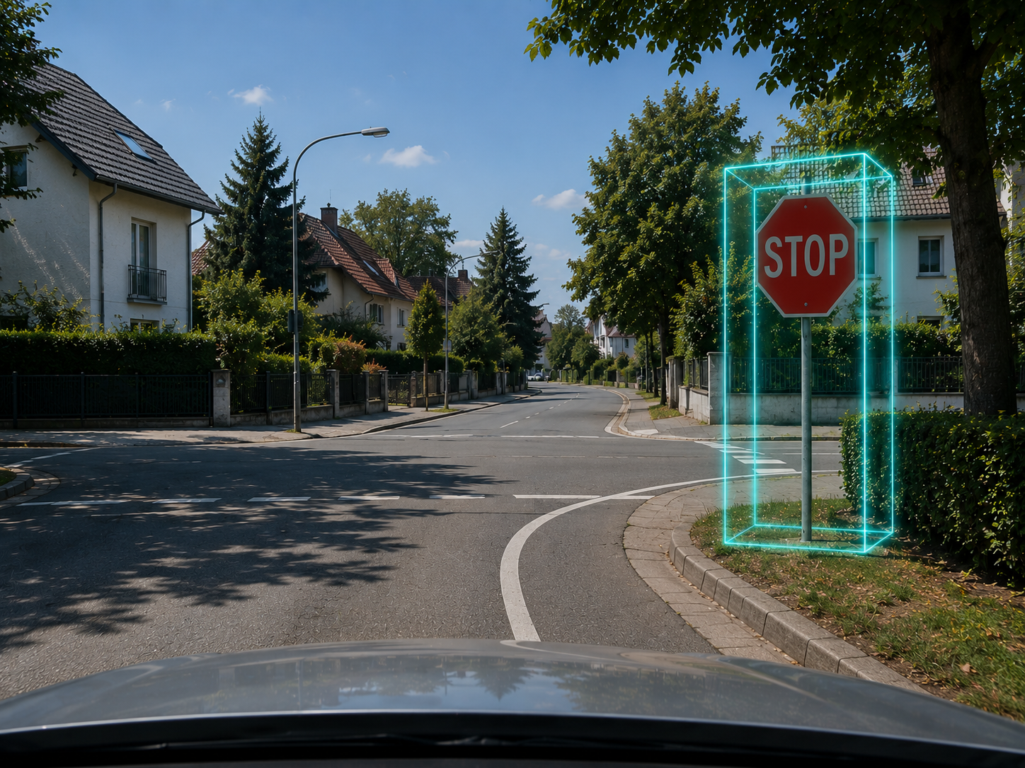
A delivery van approaches a standard intersection. The on-device neural network spots the stop sign, tracks it for a few seconds, and generates an event clip. But when your operations team reviews the video, they find the driver didn’t commit a violation at all; the stop sign was actually positioned on a parallel slip road or a cross-street lane. The vision model simply couldn’t tell which lane the sign belonged to.
This is the inherent vulnerability of relying on two-dimensional bounding boxes. A 2D box is just a boundary drawn around pixels on a flat plane. It lacks depth. When you try to build safety features like stop sign or red-light violation triggers based entirely on the expanding pixel size of an object, your dashboard quickly becomes unusable due to false positives.
We recently overhauled the visual tracking architecture under the hood of our violation detection features. Instead of guessing distance based on pixel dimensions, we introduced real-time 3D position estimation of static objects directly on the edge camera.
We managed to drive down false alerts significantly without adding expensive hardware or overloading the edge processor. Here is how we solved it from an engineering perspective.
The real-world friction of 2D tracking
In a naive video telematics setup, a camera detects a stop sign and monitors its box size as the vehicle gets closer. If the vehicle’s speed doesn’t drop to zero before that sign leaves the frame, the system flags a violation.
In production, pixel boundaries are highly unstable indicators of spatial distance. Windshield distortion, varying focal lengths, and vehicle vibrations—especially on standard fleet cameras like the Mitac K265 running wide-angle lenses—cause bounding box centers to jitter.
[Standard 2D Vision] ──► Tracks pixel box size ──► Fooled by side-street signs & vibration
[3D Edge Geometry]   ──► Tracks spatial vectors ──► Maps exact lane location in physical space
Because a flat 2D system has no concept of lateral or spatial orientation, it cannot differentiate between a sign directly in the vehicle’s path and one on an adjacent curb. To eliminate false triggers, the software must determine the exact coordinates of that physical object relative to the vehicle’s actual trajectory over time.
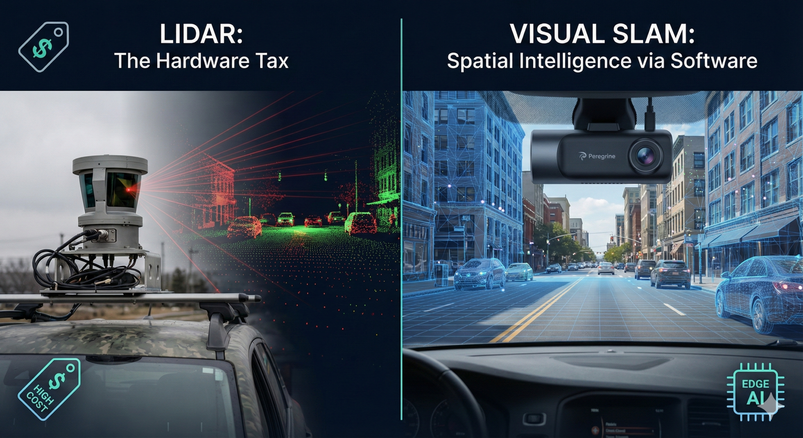
We don’t need a heavy, high-power LiDAR sensor to get these coordinates. We can extract them entirely from visual motion, provided we can isolate the real data from vehicle noise.
Stripping out rotational noise
When a vehicle moves down a street, every static object in the frame appears to expand outward from the center of the lens. This visual movement is known as optical flow. The challenge for an embedded camera is that a moving car is constantly pitching, shaking, and turning. This rotational movement pollutes the optical flow, masking the true distance of the objects you want to track.
Our updated pipeline handles this by isolating what we call residual optical flow.
We pull high-frequency camera rotation data directly from the device’s IMU. By calculating the precise orientation change between consecutive video frames, our software compensates for the vehicle’s physical tilt and vibration. We shift the coordinates from the previous frame to align with the new frame, effectively erasing the visual noise caused by a bumpy road or a sudden turn.
Once this rotation is cleared, the remaining visual expansion is entirely radial. It points cleanly away from the camera’s optical center, driven solely by the vehicle’s forward translation.
Computing a low-power depth proxy
After removing rotation, the speed at which an object expands across frames tells you how close or far it is. The faster it expands, the closer the object.
To compute this absolute depth on constrained automotive processors without triggering thermal throttling, we apply a classic robotic constraint: a non-holonomic motion model. Because a commercial delivery van or passenger car moves almost entirely forward—with negligible vertical hopping or instantaneous lateral sliding—we can remove those directional variables from our tracking logic.
By narrowing the focus to pure forward translation, we can calculate a scale-invariant inverse-depth proxy using basic pixel displacement.
This geometric shortcut allows our edge software to compute relative depth using minimal CPU cycles. When we combine this relative depth with concurrent vehicle speed metrics (from GPS or vehicle telemetry), the camera scales the proxy into absolute distance, pinpointing the stop sign in meters.
The temporal filter: Why false positives dropped
This geometric framework lives and dies by tracking stability. A single frame-level depth estimation is still vulnerable to brief tracking blips. The real breakthrough in reducing false alerts comes from how we handle the object over time across multiple frames, utilizing our sort tracker system.
As the vehicle approaches the intersection, our pipeline generates a continuous sequence of 3D position candidates for the targeted stop sign. Instead of running a basic average, we pass these coordinates through a specialized spatial filter that uses a weighted temporal average:
- Early Detections (Far Away): Pixel displacement between frames is incredibly small. The signal-to-noise ratio is low, meaning early depth calculations are less accurate. The filter assigns these points a low weight.
- Late Detections (Close Up): As the vehicle nears the intersection, the visual displacement grows significantly larger and cleaner, giving us highly precise spatial data. The filter weights these close-up detections much higher.
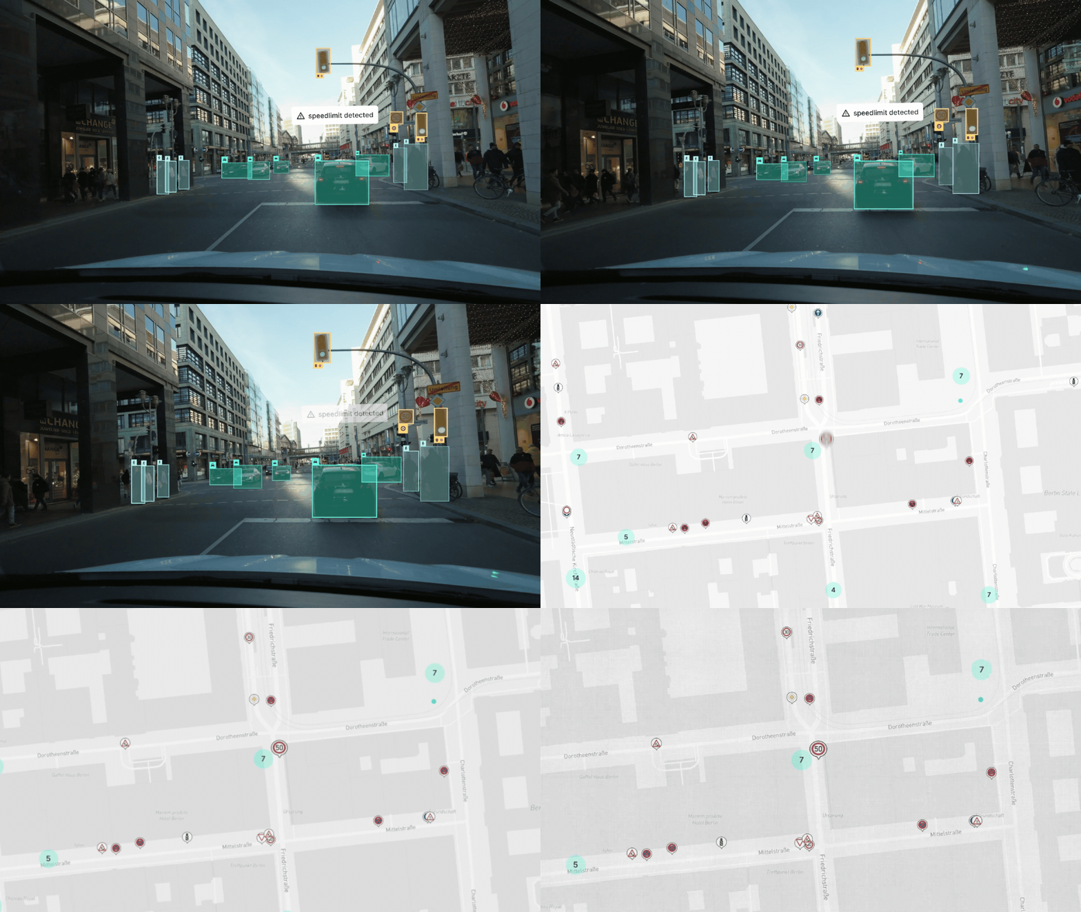
By prioritizing these high-displacement, late-stage frames, the edge software successfully filters out spatial outliers caused by tracking drift or temporary occlusions. The system projects a highly stable, filtered 3D position of the asset into a fixed world coordinate space.
The camera knows exactly which lane the sign belongs to and precisely where the vehicle needs to come to a halt.
Anchoring vision in physical space
Reliable video telematics cannot exist on simple 2D object recognition alone. Knowing a stop sign is visible in a video clip is useless if your software cannot identify where it sits in physical space relative to the driver’s path.
By anchoring flat visual inputs to on-device geometric physics, we have removed the tracking instabilities that cause false violations. For fleet operators, this eliminates dashboard alert fatigue and driver friction, replacing pixel guesswork with reliable engineering data.